EP0368705A1 - Ski boot comprising a bottom shell supporting at least one articulating upper element - Google Patents
Ski boot comprising a bottom shell supporting at least one articulating upper element Download PDFInfo
- Publication number
- EP0368705A1 EP0368705A1 EP89402871A EP89402871A EP0368705A1 EP 0368705 A1 EP0368705 A1 EP 0368705A1 EP 89402871 A EP89402871 A EP 89402871A EP 89402871 A EP89402871 A EP 89402871A EP 0368705 A1 EP0368705 A1 EP 0368705A1
- Authority
- EP
- European Patent Office
- Prior art keywords
- spring
- shoe
- rear cover
- axis
- shoe according
- Prior art date
- Legal status (The legal status is an assumption and is not a legal conclusion. Google has not performed a legal analysis and makes no representation as to the accuracy of the status listed.)
- Granted
Links
Images
Classifications
-
- C—CHEMISTRY; METALLURGY
- C09—DYES; PAINTS; POLISHES; NATURAL RESINS; ADHESIVES; COMPOSITIONS NOT OTHERWISE PROVIDED FOR; APPLICATIONS OF MATERIALS NOT OTHERWISE PROVIDED FOR
- C09K—MATERIALS FOR MISCELLANEOUS APPLICATIONS, NOT PROVIDED FOR ELSEWHERE
- C09K5/00—Heat-transfer, heat-exchange or heat-storage materials, e.g. refrigerants; Materials for the production of heat or cold by chemical reactions other than by combustion
- C09K5/02—Materials undergoing a change of physical state when used
- C09K5/06—Materials undergoing a change of physical state when used the change of state being from liquid to solid or vice versa
- C09K5/063—Materials absorbing or liberating heat during crystallisation; Heat storage materials
-
- A—HUMAN NECESSITIES
- A43—FOOTWEAR
- A43B—CHARACTERISTIC FEATURES OF FOOTWEAR; PARTS OF FOOTWEAR
- A43B7/00—Footwear with health or hygienic arrangements
- A43B7/02—Footwear with health or hygienic arrangements with heating arrangements
Definitions
- the present invention relates to an alpine ski or touring boot of the type comprising a shell bottom on which is hinged su least an upper element, movable such as rear or front cover to allow putting on and taking off, this shoe comprising a source of energy, an energy consuming device such as a heating device and a device controlling the energy supply of the consuming device
- Ski boots are already known in which are incorporated, in order to improve the comfort of the wearer of the heating devices either of the electric type, with heating resistance, or of the liquid or gaseous fuel type, which in this case use a fuel tank and a burner housed in the shoe.
- Liquid or gaseous fuel heating devices have the advantage, compared to electric devices, of obtaining greater autonomy and ensuring, for a relatively long period of time, the desired comfort temperature at inside of the shoe.
- Heating devices using liquid fuel generally include a rechargeable liquid fuel burner, which is arranged under a diffusion plate heat incorporated into the sole of the shoe so as to extend as close as possible to the foot of the wearer of the shoe.
- Other heating devices which use a gaseous fuel include a gas tank supplying, through a valve, a catalytic burner, all these elements also being completely housed in the sole of the shoe.
- gaseous fuel heating devices are described, for example, in the Italian utility model 196850 and in international patent application WO86 / 05663. These gaseous fuel heating devices are of the type with a rechargeable gas tank and it is therefore necessary to provide, in the sole of the shoe which contains the tank, an orifice through which the internal gas tank can be connected to an external gas recharge source.
- the present invention aims to remedy these drawbacks by providing a shoe provided with means that automatically cut off the power supply as soon as the wearer of the shoe leaves it.
- this alpine ski or touring boot of the type comprising a shell bottom on which is articulated at least one movable upper element, such as rear or front cover to allow putting on and taking off, this shoe comprising a source of energy, an energy consuming device, such as a heating device and a device controlling the energy supply to the consuming device, is characterized in that it comprises means of connection between the movable upper element and the device controlling the power supply in order to authorize the supply of energy to the consumer device only when the movable element of the shoe is closed and to automatically cut off this supply as soon as the movable element of the shoe is open.
- the invention applies more particularly to a shoe provided with an incorporated heating device.
- This heating device can be of the electrical type and in this case the connecting means act on an electrical switch connected between a source of electrical energy and a heating resistance.
- the heating device can also be of the liquid or gaseous fuel type and in this case the connecting means act on a tap or a valve connected between a gas or combustible liquid tank and a burner.
- the alpine ski boot according to the invention which is shown on lines 1 to 4 is of the rear entry type.
- This shoe comprises a shell base 1 on which is articulated a rear cover 2, about a lower horizontal axis and transverse 3.
- This axis 3 extends somewhat back of the upper end portion of the rear wall 1a of the shell bottom 1.
- the boot is provided with a heating device which, in the case of the non-limiting embodiment presently described, is of the combustible gas type.
- the heating device comprises a heating assembly 4 which is housed in a suitably shaped recess provided in the upper part of the sole 5 of the shoe.
- This heating assembly 4 comprises a burner 6 fixed, for example by welding, under a heat diffusion plate 7 itself placed under the inner sole 8 of the boot, in order to be able to heat the skier's foot in very cold weather.
- the burner 6 is connected to a gas supply tube 11 and the ignition of the gas is carried out by means of an electrode 13 adjacent to the burner 3 and forming part of an ignition device, for example of the piezo type. electric.
- the heating assembly 4 is supplied with gas from an interchangeable fuel gas cartridge 14 which is held in a housing provided in the upper part of the rear cover 2 of the boot, inside the latter.
- the gas cartridge 14 is disposed substantially vertically with its gas outlet opening facing downward.
- the "vertical" direction is that in which the rear cover 2 extends, while in fact the rear wall 2a of this cover is slightly inclined towards the front.
- the gas cartridge 14 is connected, at its lower end, to an assembly 15 forming a tap and regulator connected, at its lower part to the gas supply tube 11.
- This tube made of flexible material, passes through an opening 2 b spared in the transverse bottom wall 2 c of the cover 2 which is inclined from top to bottom and from back to front and which extends towards the upper part of the rear wall 1a of the shell base 1.
- the tube 11 outputs and partly of the hood 2 and re-enters the shoe passing through an opening 1b formed in the back wall 1 a of the lower shell, to extend to the burner 6 housed in the sole.
- the valve 15 opening and closing control member is constituted by a finger 16 protruding outside the body of the valve 15 and movable in a vertical lumen of this body.
- the finger 16 is pushed down, towards its open position, by a return spring 17 housed inside the pressure-reducing valve 15.
- the finger 16 for controlling the valve 15 is actuated by a tab 18 making part of a heating control device 19.
- This device 19 also acts on a pusher 21 of an igniter 22, for example of the piezoelectric type, which is connected, by an electrical conductor not shown, to the electrode 13 in order to produce an ignition spark.
- the heating control device comprises a control button 23 which can slide "vertically" outside the rear wall 2a of the cover 2.
- the control button 23 is fixed to a tab 24 extending through a vertical light 25 formed in the rear wall 2 a of the cover 2.
- the tab 24 constitutes the external extension of a voluntary unlocking plate 26 extending vertically.
- This voluntary unlocking plate 26 comprises, a vertical core 26a and at its upper part, a vertical wing 26b extended by a horizontal wing 26c which extends a short distance in the gas closed position, which is shown in FIG. 4, above the upper pusher 21 of the piezoelectric igniter 22 fixed to the cover 2.
- the voluntary unlocking plate 26 comprises a lower horizontal wing 26d which is extended downwards by a bar 26e ending in a release ramp lock 27 which acts on the horizontal web of the upper part 28a, shaped strap or inverted U, with a locking spring 28.
- the locking spring 28 is fixed to the upper part of the rear wall 1a of the shell bottom 1 of the shoe. It comprises, below its upper strap 28a, two parallel branches 28b extending downward and inclined relative to the upper strap by forming an obtuse angle open towards the front.
- Each of the two branches 28b is connected to a helical part 28c of the spring 28 wound around the axis 3 of articulation of the rear cover 2 and ending in an extreme anchoring branch 28d extending downwards and immobilized in a housing provided in the upper part of the rear wall 1 a of the shell 1.
- the heating control device also comprises a second locking plate 32 which is attached to the voluntary unlocking plate 26 and which has a C shape open towards the rear.
- the two plates 26 and 32 are coupled to each other by means of guide pins 33 provided on the core 26a of the voluntary unlocking plate 26, these pins 33 being engaged in slots 34 formed in the 'soul of the other plate 32, these lights 34 being aligned and elongated vertically.
- the lower horizontal wing of the locking plate 32 is extended downwards by a bar which ends in a locking hook 35 capable of coming to grip under the web of the upper part 28a of the locking spring 28.
- the locking plate 32 carries, at its lower part, the tab 18, projecting which actuates, from below, the finger 16 controlling the opening and closing of the tap 15.
- the two plates 26, 32 are biased jointly upwards by a return spring 36 which is constituted by a compression spring bearing, at its lower end, on a shoulder 37 provided on the internal face of the rear wall 2a of the cover. 2 and, at its upper end, both under the upper horizontal wings of the plates 26 and 32.
- the spring 36 biases thus constantly the two plates 26,32 upwards and their movement in this direction is limited by the abutment of the lower wings of the plates 26,32 under the bearing shoulder 37.
- the control button 23 can occupy, in the light 25, three different vertical positions, namely an upper extreme position I, corresponding to the closing of the gas supply, an intermediate position II, corresponding to the opening of the supply. in gas, and an extreme lower position III, corresponding to the actuation of the piezoelectric igniter 22, these three positions I, II, III being indicated in phantom in Figure 1.
- both plates 26,32 are in the extreme upper position ( Figure 4), in which they are pushed back by the return spring 36, their upward movement being limited by the abutment of their lower wings against the shoulder of support 37.
- the upper horizontal wing 26c of the plate 26 is located a short distance above the pusher 21 of the piezoelectric igniter 22.
- the control button 23 drives with it the voluntary unlocking plate 26 with which it is integral and this in turn immediately drives the locking plate 32, owing to the fact that the guide pins 33 which are integral with the plate 26, are in contact with the lower ends of the slots 34 formed in the plate 32.
- the two plates 26, 32 are thus moved jointly downwards, against the action of the return spring 36.
- the locking hook 35 slides along the core of the upper part 28a of the spring 28 while pushing it back slightly, after which it comes to be placed under this core to ensure locking.
- the unlocking ramp 27 naturally accompanies this movement.
- valve control finger 16 15 releases the valve control finger 16 15 so that this valve opens. Consequently, as soon as the control button 23 reaches the intermediate position II, the valve 15 is open and the gas contained in the interchangeable cartridge 13 can then flow through the pipe 11 towards the burner 6 of the heating assembly 4.
- the skier presses the control button 23 fully so as to bring it into its extreme lower position III.
- the upper horizontal wing 26c of the plate 26 which was then, in the intermediate position II, just in contact with the upper end of the pusher 21, pushes this pusher down and causes actuation of the piezoelectric igniter 22 which emits an electrical pulse giving rise to an ignition spark produced by the electrode 13.
- the unlocking ramp 27 and the hook 35 are moved slightly below the core of the upper part 28a of the spring 28.
- the control button 23 When the skier wishes to stop the heating, he pulls the control button 23 upwards to return it to its extreme upper closing position I. During this closing phase, the control button 23 firstly causes the sliding upwards of the single voluntary unlocking plate 26, due to the coupling produced by the guide pins 33 and the slots 34, these pins 33 moving n upwards alone in the lights 34 remaining stationary. As a result of this movement, the lower unlocking ramp 27 of the voluntary unlocking plate 26 which slides in contact with the core of the upper part 28a of the spring 28, gradually pushes this core inwards, thereby gradually removing the spring. until the locking hook 35 can escape it.
- the slope of the unlocking ramp 27 and its length are chosen such that the escape of the locking hook 35 occurs before the guide pins 33 reach the upper ends of the slots 34.
- the shoe is provided with means automatically causing the gas supply to be cut off as soon as the wearer of the shoe leaves it.
- These means consist, in the non-limiting embodiment shown in Figures 1 to 4, by the combination of the inclined lower wall 2c of the rear cover 2 and the locking spring 28.
- the spring 28 is or is not armed in the locked position.
- its inclined lower wall 2c biases the spring 28 forward and more particularly the branches 28b of this spring, forming it and by subjecting it consequently to an elastic pre-stress.
- the upper part 28a in the form of a loop of the spring 28 is placed and maintained in a position such that it allows the hooking of the locking hook 35 from the locking plate 33.
- the tilting of the hood 2 has the consequence that at a certain time during this tilting movement the locking hook 35, previously hooked under the core of the upper part 28a of the spring 28 escapes this spring so that the two sliding plates 22,33 are pushed upwards by the spring of c compression 36.
- the tab 18 then pushes upwards the finger 16 for controlling the valve 15 which causes the valve to close and the gas supply to be automatically cut off. .
- the two helical parts 28c of the spring 28 which are wound on the articulation axis 3, end respectively by end branches 28e extending upwards and 28f extending down, these two arms being substantially coplanar and being in abutment against the outer and upper side of the rear wall 1 a shell base 1. for the rest the spring 28 is made in the same manner as in the case of shoe illustrated in FIGS. 1 to 4, the upper part 28a of the spring 28 being urged forward by the inclined lower wall born 2c from the back cover 2.
- the rear cover 2 is articulated, on the bottom of the shell 1, around a transverse lower axis 39 which is located in front of the rear wall 1 a of the bottom of the shell 1.
- the helical parts 28c of the spring 28 are wound around a transverse axis 3 which is provided in the lower part of the rear cover 2 and which is used only for mounting the spring 28.
- the spring 28 is also produced from the as illustrated in Figure 5, that is to say that it comprises two end branches 28e, 28f extending respectively upwards and downwards from the helical parts 28c.
- the shoe has a rod made up of two parts articulated on the bottom of the shell 1 around the common transverse axis 3, namely the rear cover 2 and a front cuff 41.
- the extreme branches 28d which extend the helical parts 28c of the spring 28 wound on the axis 3 are anchored at their ends, in parts of the cuff 41 close to the hinge pin 3
- the anchoring points of the ends of the spring 28 on the cuff 41 are arranged in such a way that this spring is armed, or prestressed when the rear cover 2 is in the closed position Consequently when the skier opens the upper of his boot by tilting the hood 2 towards the rear, the spring 28 is automatically disarmed and it then releases the locking hook 25 thereby causing the automatic cut off of the gas supply.
- FIG. 8 represents an alternative embodiment of the invention applied to a ski boot comprising on its front and top face a front tongue 42 which is articulated at its bottom and front part on a front and top wall 1d of the bottom of the shell 1 and this around a horizontal and transverse axis 43
- the assembly constituted by the gas cartridge 14 and the device 19 controlling the gas supply is mounted under the front tongue 42 extending in a vertical and longitudinal plane
- the locking hook 35 which s extends towards 1 before then cooperates with the posterior end portion 44a in the form of a loop, with a locking spring 44.
- This spring 44 comprises two parallel lower branches 44b by which it is anchored in the wall 1d of the bottom of the shell 1 and which are inclined from bottom to top and from front to back
- These extreme anchoring branches 44b form an obtuse angle open upwards with the upper part f forming a loop 44a which is consequently inclined further from bottom to top and from front to back
- the locking hook 35 then comes to grip behind the upper horizontal core of this portion in the form of a loop 44a Due to this construction when the skier opens his shoe by tilting the front tongue 42 anti-clockwise around the axis 43 the locking hook 35 escapes from the upper part 44a of the spring 44 which causes, as in the embodiments previously described automatic shutdown of the gas supply.
- the flexible gas supply pipe 11 extends, inside the boot from the supply control device 19 downwards and forwards under the inclined upper wall 1d of the bottom of the hull 1 then vertically along the front front wall 1 e of the bottom of the hull then horizontally backwards under the insole 8 to reach the burner 6.
Abstract
Description
La présente invention concerne une chaussure de ski alpin ou de randonnée du type comportant un bas de coque sur lequel est articulé su moins un élément supérieur, mobile tel que capot arrière ou avant pour permettre le chaussage et le déchaussage, cette chaussure comportant une source d'énergie, un dispositif consommateur d'énergie tel qu'un dispositif de chauffage et un dispositif commandant l'alimentation en énergie du dispositif consommateurThe present invention relates to an alpine ski or touring boot of the type comprising a shell bottom on which is hinged su least an upper element, movable such as rear or front cover to allow putting on and taking off, this shoe comprising a source of energy, an energy consuming device such as a heating device and a device controlling the energy supply of the consuming device
On connait déjà des chaussures de ski dans lesquelles sont incorporés, dans le but d'améliorer le confort du porteur des dispositifs de chauffage soit du type électrique, à résistance chauffante, soit du type à combustible liquide ou gazeux, qui utilisent dans ce cas un réservoir de combustible et un brûleur logés dans la chaussure. Les dispositifs de chauffage à combustible liquide ou gazeux présentent l'avantage, par rapport aux dispositifs électriques, de permettre d'obtenir une plus grande autonomie et d'assurer, pendant une période de temps relativement longue, la température de confort désirée à l'intérieur de la chaussure.Ski boots are already known in which are incorporated, in order to improve the comfort of the wearer of the heating devices either of the electric type, with heating resistance, or of the liquid or gaseous fuel type, which in this case use a fuel tank and a burner housed in the shoe. Liquid or gaseous fuel heating devices have the advantage, compared to electric devices, of obtaining greater autonomy and ensuring, for a relatively long period of time, the desired comfort temperature at inside of the shoe.
Les dispositifs de chauffage utilisant un combustible liquide, tels que décrits, par exemple, dans les brevets II-I 136 269 et FR-A-2 080 146, comportent généralement un bruleur à combustible liquide rechargeable, lequel est disposé sous une plaque de diffusion de la chaleur incorporée dans la semelle de la chaussure de manière à s'étendre le plus près possible du pied du porteur de la chaussure. D'autres dispositifs de chauffage qui utilisent un combustible gazeux, comprennent un réservoir de gaz alimentant, à travers une vanne, un bruleur catalytique, tous ces éléments étant également logés en totalité dons la semelle de la chaussure. De tels dispositifs de chauffage à combustible gazeux sont décrits, par exemple, dons le modèle d'utilité italien 196850 et dans la demande de brevet internationale WO86/05663. Ces dispositifs de chauffage à combustible gazeux sont du type à réservoir de gaz rechargeable et il est nécessaire par conséquent de prévoir, dans la semelle de la chaussure qui contient le réservoir, un orifice à travers lequel le réservoir de gaz interne peut être raccordé à une source de recharge en gaz externe.Heating devices using liquid fuel, as described, for example, in patents II-I 136 269 and FR-A-2 080 146, generally include a rechargeable liquid fuel burner, which is arranged under a diffusion plate heat incorporated into the sole of the shoe so as to extend as close as possible to the foot of the wearer of the shoe. Other heating devices which use a gaseous fuel, include a gas tank supplying, through a valve, a catalytic burner, all these elements also being completely housed in the sole of the shoe. Such gaseous fuel heating devices are described, for example, in the Italian utility model 196850 and in international patent application WO86 / 05663. These gaseous fuel heating devices are of the type with a rechargeable gas tank and it is therefore necessary to provide, in the sole of the shoe which contains the tank, an orifice through which the internal gas tank can be connected to an external gas recharge source.
Tous les dispositifs de chauffage connus, qu'ils soient du type électrique ou à combustible liquide ou gazeux présentent l'inconvénient qu'une fois le chauffage mis en marche, l'arrêt de ce chauffage ne peut être obtenu que par intervention manuel le du porteur de la chaussure. Autrement dit celui-ci doit penser à couper le chauffage lorsqu'il quitte sa chaussure et il peut évidemment arriver qu'il oublie de procéder à cette manoeuvre, ce qui se traduit alors par une poursuite du chauffage de la chaussure déchsussée, d'où un épuisement rapide de la source d'énergie utilisée et un gaspillage de cette énergie.All known heating devices, whether of the electric or liquid or gaseous fuel type have the disadvantage that once the heating is started, the stopping of this heating can only be obtained by manual intervention on the shoe wearer. In other words, the latter must think of cutting the heating when he leaves his shoe and it can obviously happen that he forgets to carry out this maneuver, which then results in a continuation of the heating of the disheveled shoe, whence a rapid exhaustion of the energy source used and a waste of this energy.
La présente invention vise à remédier à ces inconvénients en procurant une chaussure pourvue de moyens provoquant automatiquement la coupure de l alimentation en énergie aussitôt que le porteur de la chaussure quitte celle-ci.The present invention aims to remedy these drawbacks by providing a shoe provided with means that automatically cut off the power supply as soon as the wearer of the shoe leaves it.
A cet effet cette chaussure de ski alpin ou de randonnée du type comportant un bas de coque sur lequel est articulé au moins un élément supérieur mobile, tel que capot arrière ou avant pour permettre le chaussage et le déchaussage, cette chaussure comportant une source d'énergie, un dispositif consommateur d'énergie, tel qu'un dispositif de chauffage et un dispositif commandant l'alimentation en énergie du dispositif consommateur, est caractérisée en ce qu'elle comprend des moyens de liaison entre l'élément supérieur mobile et le dispositif commandant l'alimentation en énergie afin d'autoriser l'alimentation en énergie du dispositif consommateur uniquement lorsque l'élément mobile de la chaussure est fermé et de provoquer automatiquement la coupure de cette alimentation aussitôt que l'élément mobile de la chaussure est ouvert.To this end, this alpine ski or touring boot of the type comprising a shell bottom on which is articulated at least one movable upper element, such as rear or front cover to allow putting on and taking off, this shoe comprising a source of energy, an energy consuming device, such as a heating device and a device controlling the energy supply to the consuming device, is characterized in that it comprises means of connection between the movable upper element and the device controlling the power supply in order to authorize the supply of energy to the consumer device only when the movable element of the shoe is closed and to automatically cut off this supply as soon as the movable element of the shoe is open.
L'invention s'applique plus particulièrement à une chaussure pourvue d'un dispositif de chauffage incorporé. Ce dispositif de chauffage peut être du type électrique et dans ce cas les moyens de liaison agissent sur un interrupteur électrique branché entre une source d'énergie électrique et une résistance chauffante. Le dispositif de chauffage peut être également du type à combustible liquide ou gazeux et dans ce cas les moyens de liaison agissent sur un robinet ou une vanne branchée entre un réservoir de gaz ou liquide combustible et un brûleur.The invention applies more particularly to a shoe provided with an incorporated heating device. This heating device can be of the electrical type and in this case the connecting means act on an electrical switch connected between a source of electrical energy and a heating resistance. The heating device can also be of the liquid or gaseous fuel type and in this case the connecting means act on a tap or a valve connected between a gas or combustible liquid tank and a burner.
On décrira ci-après, à titre d'exemple non limitatif une forme exécution de la présente invention en référence au dessin annexé sur lequel :
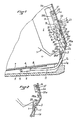
- La figure 1 est une vue en coupe verticale et longitudinale partielle d'une chaussure de ski alpin à entrée arrière pourvue d'un dispositif de chauffage à gaz, le capot arrière étant représenté en position de fermeture et le dispositif de commande de l'alimentation en gaz étant en position d'ouverture.
- La figure 2 est une vue en coupe verticale et longitudinale partielle de la chaussure avec le capot arrière fermé, le dispositif de commande de l'alimentation en gaz étant représenté dans une position intermédiaire, en cours de déverrouillage, avant son retour en position de fermeture.
- La figure 3 est une vue en coupe verticale et longitudinale partielle de la chaussure avec le capot arrière fermé, le dispositif de commande de l'alimentation en gaz étant représenté en position d'allumage.
- La figure 4 est une vue en coupe verticale et longitudinale partielle de la chaussure avec le capot arrière ouvert et le dispositif de commande d'alimentation en gaz rappelé automatiquement en position d'ouverture.
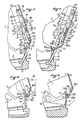
- Les figures 5 et 6 sont des vues en coupe longitudinale partiel les de variantes d'exécution d'une chaussure à capot arrière basculant suivant l'invention.
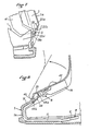
- La figure 7 est une vue en coupe verticale et longitudinale partielle d'une variante d'exécution d'une chaussure comportant une manchette avant et un capot arrière articulés autour d'un même axe.
- La figure 8 est une vue en coupe verticale et longitudinale partielle d'une chaussure suivant l'invention com portant une languette ou capot avant en tant qu'élément mobile supérieur.
- Figure 1 is a partial vertical and longitudinal sectional view of an alpine ski boot with rear entry provided with a gas heating device, the rear cover being shown in the closed position and the power control device in gas being in the open position.
- Figure 2 is a partial vertical and longitudinal sectional view of the shoe with the rear cover closed, the gas supply control device being shown in an intermediate position, during unlocking, before returning to the closed position .
- Figure 3 is a partial vertical and longitudinal sectional view of the shoe with the rear cover closed, the gas supply control device being shown in the ignition position.
- Figure 4 is a partial vertical and longitudinal sectional view of the shoe with the rear cover open and the gas supply control device automatically returned to the open position.
- Figures 5 and 6 are views in partial longitudinal section of alternative embodiments of a shoe with tilting rear cover according to the invention.
- Figure 7 is a partial vertical and longitudinal sectional view of an alternative embodiment of a shoe comprising a front cuff and a rear cover articulated around the same axis.
- Figure 8 is a partial vertical and longitudinal sectional view of a shoe according to the invention com carrying a tongue or front cover as an element upper mobile.
La chaussure de ski alpin suivant l'invention qui est représentée sur les lignes 1 à 4 est du type à entrée arrière. Cette chaussure comprend un bas de coque 1 sur lequel est articulé un capot arrière 2, autour d'un axe inférieur horizontal et transversal 3. Cet axe 3 s'étend un peu en arrière de la partie extrême supérieure de la paroi postérieure 1a du bas de coque 1. La chaussure est pourvue d'un dispositif de chauffage qui, dans le cas de la forme d'exécution non limitative présentement décrite, est du type à gaz combustible. Toutefois l'invention s'appliquerait de la même façon à une chaussure pourvue d'un dispositif de chauffage électrique ou à combustible liquide. Le dispositif de chauffage comprend un ensemble chauffant 4 qui est logé dans un évidement de forme appropriée prévu dans la partie supérieure de la semelle 5 de la chaussure. Cet ensemble chauffant 4 comprend un brûleur 6 fixé, par exemple par soudage, sous une plaque de diffusion de la chaleur 7 elle-même placée sous la semelle interne 8 de la chaussure, afin de pouvoir chauffer le pied du skieur par grand froid. Le brûleur 6 est relié à un tube d'alimentation en gaz 11 et l'allumage du gaz est réalisé au moyen d'une électrode 13 voisine du brûleur 3 et faisant partie d'un dispositif d'allumage, par exemple du type piézo-électrique.The alpine ski boot according to the invention which is shown on lines 1 to 4 is of the rear entry type. This shoe comprises a shell base 1 on which is articulated a
L'ensemble chauffant 4 est alimenté en gaz à partir d'une cartouche de gaz combustible interchangeable 14 qui est maintenue dans un logement prévu dans la partie supérieure du capot arrière 2 de la chaussure, à l'intérieur de celui-ci. La cartouche de gaz 14 est disposée sensiblement verticalement avec son orifice de sortie du gaz dirigé vers le bas. Dans la description qui va suivre on considérera que le sens "vertical" est celui suivant lequel s'étend le capot arrière 2 alors qu'en fait la paroi postérieure 2a de ce capot est légèrement inclinée vers l'avant. La cartouche de gaz 14 est raccordée, à son extrémité inférieure, à un ensemble 15 formant robinet et détendeur relié, à sa partie inférieure au tube d'alimentation en gaz 11. Ce tube, en matière souple, passe à travers une ouverture 2b ménagée dans la paroi inférieure transversale 2c du capot 2 qui est inclinée de haut en bas et d'arrière en avant et qui s'étend en direction de la partie supérieure de la paroi postérieure 1a du bas de coque 1. Le tube 11 sort ainsi partiellement du capot 2 et il pénètre de nouveau dans la chaussure en passant à travers une ouverture 1b formée dans la paroi postérieure 1a du bas de coque, pour s'étendre jusqu'au brûleur 6 logé dans la semelle.The heating assembly 4 is supplied with gas from an interchangeable
L'organe de commande d'ouverture et de fermeture du robinet 15 est constitué par un doigt 16 faisant saillie à l'extérieur du corps du robinet 15 et mobile dans une lumière verticale de ce corps. Le doigt 16 est repoussé vers le bas, en direction de sa position d'ouverture, par un ressort de rappel 17 logé à l'intérieur du robinet-détendeur 15. Le doigt 16 de commande du robinet 15 est actionné par une patte 18 faisant partie d'un dispositif 19 de commande du chauffage. Ce dispositif 19 agit également sur un poussoir 21 d'un allumeur 22, par exemple du type piézo électrique, qui est relié, par un conducteur électrique non représenté, à l'électrode 13 afin de produire une étincelle d'allumage.The
Le dispositif de commande du chauffage comprend un bouton de commande 23 qui peut coulisser "verticalement" à l'extérieur de la paroi postérieure 2a du capot 2. Le bouton de commande 23 est fixé à une patte 24 s étendant à travers une lumière verticale 25 ménagée dans la paroi postérieure 2a du capot 2. La patte 24 constitue le prolongement externe d'une platine de déverrouillage volontaire 26 s'étendant verticalement. Cette platine de déverrouillage volontaire 26 comprend, une âme verticale 26a et à sa partie supérieure, une aile verticale 26b prolongée par une aile horizontale 26c qui s'étend à faible distance en position de fermeture du gaz, qui est représentée sur la figure 4, au-dessus du poussoir supérieur 21 de l'allumeur piézo-électrique 22 fixé au capot 2.The heating control device comprises a
La platine de déverrouillage volontaire 26 comprend une aile horizontale inférieure 26d qui est prolongée vers le bas par une barre 26e se terminant par une rampe de dé verrouillage 27 qui agit sur l'âme horizontale de la partie supérieure 28a, en forme de ganse ou de U inversé, d'un ressort de verrouillage 28. Ce ressort de verrouillage 28 est fixé à la partie supérieure de la paroi postérieure 1a du bas de coque 1 de la chaussure. Il comprend, en dessous de sa ganse supérieure 28a, deux branches parallèles 28b s'étendant vers le bas et inclinées par rapport à la ganse supérieure en formant un angle obtus ouvert vers l'avant. Chacune des deux branches 28b est reliée à une partie hélicoïdale 28c du ressort 28 enroulée autour de l'axe 3 d'articulation du capot arrière 2 et se terminant par une branche extrême d'ancrage 28d s'étendant vers le bas et immobilisée dans un logement prévu dans la partie supérieure de la paroi postérieure 1a du bas de coque 1.The
Le dispositif de commande du chauffage comporte par ailleurs une seconde platine de verrouillage 32 qui est accolée à la platine de déverrouillage volontaire 26 et qui présente une forme de C ouvert vers l'arrière. Les deux platines 26 et 32 sont accouplées l'une à l'autre par l'intermédiaire de pions de guidage 33 prévus sur l'âme 26a de la platine de déverrouillage volontaire 26, ces pions 33 étant engagés dans des lumières 34 ménagées dans l'âme de l'autre platine 32, ces lumières 34 étant alignées et allongées verticalement. L'aile horizontale inférieure de la platine de verrouillage 32 est prolongée vers le bas par une barre qui se termine par un crochet de verrouillage 35 susceptible de venir s'agripper sous l'âme de la partie supérieure 28a du ressort de verrouillage 28. Par ailleurs la platine de verrouillage 32 porte, à sa partie inférieure, la patte 18, en saillie qui actionne, par en-dessous, le doigt 16 commandant l'ouverture et fermeture du robinet 15.The heating control device also comprises a
Les deux platines 26,32 sont sollicitées conjointement vers le haut par un ressort de rappel 36 qui est constitué par un ressort de compression prenant appui, à son extrémité inférieure, sur un épaulement 37 prévu sur la face interne de la paroi postérieure 2a du capot 2 et, à son extrémité supérieure, à la fois sous les ailes horizontales supérieures des platines 26 et 32. Le ressort 36 sollicite ainsi constamment les deux platines 26,32 vers le haut et leur mouvement dans ce sens est limité par la venue en butée des ailes inférieures des platines 26,32 sous l'épaulement d'appui 37.The two
Le bouton de commande 23 peut occuper, dans la lumière 25, trois positions verticales différentes à savoir une position extrême supérieure I, correspondant à la fermeture de l'alimentation en gaz, une position intermédiaire II, correspondant à l'ouverture de l'alimentation en gaz, et une position extrême inférieure III, correspondant à l'actionnement de l'allumeur piézo-électrique 22, ces trois positions I,II,III étant indiquées en trait mixte sur la figure 1. En position supérieure de fermeture I les deux platines 26,32, se trouvent en position extrême supérieure (figure 4), dans laquelle elles sont repoussées par le ressort de rappel 36, leur mouvement vers le haut étant limité par la venue en butée de leurs ailes inférieures contre l'épaulement d'appui 37. Dans cette position l'aile horizontale supérieure 26c de la platine 26 est située à faible distance au-dessus du poussoir 21 de l'allumeur piézo-électrique 22.The
Lorsque le skieur désire mettre en marche le dispositif de chauffage, il appuie sur le bouton de commande 23 de manière à le déplacer vers le bas. Dans ce mouvement le bouton de commande 23 entraîne avec lui la platine de déverrouillage volontaire 26 dont il est solidaire et celle-ci entraîne à son tour immédiatement la platine de verrouillage 32, du fait que les pions de guidage 33 qui sont solidaires de la platine 26, se trouvent en contact avec les extrémités inférieures des lumières 34 ménagées dans la platine 32. Les deux platines 26,32 sont ainsi déplacées conjointement vers le bas, à l'encontre de l'action du ressort de rappel 36. Au cours de ce mouvement le crochet de verrouillage 35 glisse le long de l'âme de la partie supérieure 28a du ressort 28 en la repoussant quelque peu, après quoi il vient se placer sous cette âme pour assurer le verrouillage. La rampe de déverrouillage 27 accompagne naturellement ce mouvement. Dans le même temps la patte 18 de la platine 32 libère le doigt 16 de commande du robinet 15 si bien que ce robinet s'ouvre. Par conséquent, aussitôt que le bouton de commande 23 atteint la position intermédiaire II, le robinet 15 est ouvert et le gaz contenu dans la cartouche interchangeable 13 peut alors s'écouler à travers le tuyau 11 en direction du brûleur 6 de l'ensemble chauffant 4.When the skier wishes to turn on the heating device, he presses the
Pour provoquer l'allumage du mélange gaz-air, le skieur appuie à fond sur le bouton de commande 23 de manière à l'amener dans sa position extrême inférieure III. Au cours de ce mouvement de descente complémentaire, l'aile horizontale supérieure 26c de la platine 26 qui se trouvait alors, dans la position intermédiaire II, juste en contact avec l'extrémité supérieure du poussoir 21, repousse ce poussoir vers le bas et provoque l'actionnement de l'allumeur piézo-électrique 22 qui émet une impulsion électrique donnant lieu à une étincelle d'allumage produite par l'électrode 13. Au cours de ce déplacement additionnel vers le bas la rampe de déverrouillage 27 et le crochet 35 sont déplacés un peu en dessous de l'âme de la partie supérieure 28a du ressort 28. Lors du relâchement du bouton de commande 23, après allumage du gaz, les deux platines 26,32 sont repoussées vers le haut par le ressort 36 jusqu'à ce que le crochet 35 vienne s'agripper en dessous de l'âme de la partie supérieure 28a du ressort 28. A partir de ce moment les deux platines 26,32 sont immobilisées dans la position intermédiaire d'ouverture II ainsi qu'il est représenté sur la figure 1. Dans cette position la patte 18 de la platine de verrouillage 32 se trouve située juste en dessous du doigt de commande 16 du robinet 15 qui se trouve lui-même dans sa position extrême inférieure d'ouverture dans une lumière du corps du robinet.To cause the ignition of the gas-air mixture, the skier presses the
Lorsque le skieur désire arrêter le chauffage, il tire le bouton de commande 23 vers le haut pour le ramener dans sa position extrême supérieure de fermeture I. Au cours de cette phase de fermeture, le bouton de commande 23 entraine tout d'abord le coulissement vers le haut de la seule platine de déverrouillage volontaire 26, du fait de l'accouplement réalisé par les pions de guidage 33 et les lumières 34, ces pions 33 se déplaçant n lors seuls vers le haut dans les lumières 34 restant immobiles. Du fait de ce déplacement la rampe de déverrouillage inférieure 27 de la platine de déverrouillage volontaire 26 qui glisse au contact de l'âme de la partie supérieure 28a du ressort 28, repousse progressivement vers l'intérieur cette âme, en écartant ainsi progressivement le ressort jusqu'à ce que le crochet de verrouillage 35 puisse lui échapper. La pente de la rampe de déverrouillage 27 et sa longueur sont choisies de telle façon que l'échappement du crochet de verrouillage 35 se produise avant que les pions de guidage 33 n'atteignent les extrémités supérieures des lumières 34. Lorsque le crochet de verrouillage 36 échappe au ressort 28, la platine 32 est libérée et les deux platines 26,32 sont repoussées conjointement vers le haut, en position de fermeture, par le ressort 36. Dans ce mouvement la patte 18 de la platine 32 entraîne avec elle vers le haut le doigt 16 de commande du robinet 15, jusqu'à ce que celui-ci vienne se placer en position de fermeture, à l'extrémité supérieure de sa lumière de guidage.When the skier wishes to stop the heating, he pulls the
Suivant l'invention la chaussure est pourvue de moyens provoquant automatiquement la coupure de l'alimentation en gaz aussitôt que le porteur de la chaussure quitte celle-ci. Ces moyens sont constitués, dans la forme d'exécution non limitative représentée sur les figures 1 à 4, par la combinaison de la paroi inférieure inclinée 2c du capot arrière 2 et du ressort de verrouillage 28. En fait suivant la position occupée par le capot arrière 2 le ressort 28 se trouve ou non armé en position de verrouillage. En effet lorsque le capot arrière 2 est fermé ainsi qu'il est représenté sur les figures 1 à 3, sa paroi inférieure inclinée 2c sollicite vers l'avant le ressort 28 et plus particulièrement les branches 28b de ce ressort, en le dé formant et en le soumettant par conséquent à une pré-contrainte élastique. Dans cette position la partie supérieure 28a en forme de ganse du ressort 28 se trouve placée et maintenue dans une position telle qu'elle permet l'accrochage du crochet de verrouillage 35 de la platine de verrouillage 33.According to the invention the shoe is provided with means automatically causing the gas supply to be cut off as soon as the wearer of the shoe leaves it. These means consist, in the non-limiting embodiment shown in Figures 1 to 4, by the combination of the inclined
Lorsque le skieur quitte sa chaussure, il fait bas culer préalablement le capot arrière 2 vers l'arrière, autour de l'axe d'articulation 3, pour atteindre la position illustrée sur la figure 4. Au cours de ce mouvement la paroi inférieure inclinée 2c du capot arrière 2 libère les deux branches 28b du ressort 28 qui peut alors se détendre et au cours de la poursuite du mouvement de basculement du capot 2 vers l'arrière, le crochet de verrouillage 35 se trouve écarté de la partie supérieure 28a du ressort 28 comme il apparaît sur la figure 4. Par conséquent si, au moment où le skieur fait basculer le capot 2 vers l'arrière, le dispositif de chauffage se trouve être en fonctionnement, le basculement du capot 2 a pour conséquence qu'à un certain moment au cours de ce mouvement de basculement le crochet de verrouillage 35, précédemment accroché sous l'âme de la partie supérieure 28a du ressort 28 échappe à ce ressort si bien que les deux platines coulissantes 22,33 sont repoussées vers le haut par le ressort de compression 36. Comme dans, le cas d'une action volontaire, la patte 18 repousse a lors vers le haut le doigt 16 de commande du robinet 15 ce qui entraîne la fermeture de celui-ci et la coupure automatique de l'alimentation en gaz.When the skier leaves his shoe, it is low previously tilt the
Lors du chaussage le basculement du capot 2 vers l'avant provoque de nouveau une sollicitation du ressort 28 vers l'avant, sous l'action de la paroi inclinée 2c du capot 2, et la partie supérieure 28a de ce ressort reprend alors la position appropriée permettant l'accrochage du crochet de verrouillage 35.When putting on the
Dans la variante d'exécution représentée sur la figure 5 les deux parties hélicoïdales 28c du ressort 28 qui sont enroulées sur l'axe d'articulation 3, se terminent respectivement par des branches extrêmes 28e s'étendant vers le haut et 28f s'étendant vers le bas, ces deux branches étant sensiblement coplanaires et étant en appui contre la face externe et supérieure de la paroi postérieure 1a du bas de coque 1. Pour le reste le ressort 28 est réalisé de la même façon que dans le cas de la chaussure illustrée sur les figures 1 à 4, la partie supérieure 28a du ressort 28 étant sollicitée vers l'avant par la paroi inférieure incli née 2c du capot arrière 2.In the variant shown in FIG. 5, the two
Dans la variante d'exécution représentée sur la figure 6 le capot arrière 2 est articulé, sur le bas de coque 1, autour d'un axe inférieur transversal 39 qui est situé en avant de la paroi postérieure 1a du bas de coque 1. Dans ce cas les parties hélicoïdales 28c du ressort 28 sont enroulées au tour d'un axe transversal 3 qui est prévu à la partie inférieure du capot arrière 2 et qui sert uniquement su montage du ressort 28. Le ressort 28 est par ailleurs réalisé de la façon illustré sur la figure 5, c'est-à-dire qu'il comprend deux branches extrêmes 28e,28f s'étendant respectivement vers le haut et vers le bas à partir des parties hélicoïdales 28c. Ces deux branches extrêmes 28e,28f sont en appui, lorsque le capot arrière est fermé, comme il est représenté sur la figure 6, contre la face supérieure et postérieure de la paroi 1a du bas de coque 1, au-dessus d'un creux 1c ménagé dons cette face en assurant ainsi le maintien du ressort 28 à l'état armé, sous l'action de la paroi inférieure inclinée 2c du capot arrière 2. Lorsque le capot 2 est basculé vers l'arrière autour de l'axe transversal 39, l'axe 3 et le ressort 28 qu'il porte suivent ce mouvement et s'abaissent progressivement. A un certain moment su cours de ce mouvement de descente les deux branches 28e,28f du ressort 28 arrivent en regard d'un creux 1c prévu dans la partie inférieure de la face postérieure de la paroi la du bas de coque. Le ressort 28 se trouve alors désarmé et sa partie supérieure 28a est libérée et peut pivoter librement autour de l'axe 3, en provoquant alors automatiquement le déverrouillage du crochet 35 et la coupure automatique de l'alimentation en gaz comme dans le cas des formes d'exécutions précédemment décrites.In the variant shown in FIG. 6, the
Dans la variante d'exécution représentée sur la figure 7 la chaussure comporte une tige constituée en deux parties articulées sur le bas de coque 1 autour de l'axe transversal commun 3, à savoir le capot arrière 2 et une manchette avant 41. Dans ce cas les branches extrêmes 28d qui prolongent les parties hélicoïdales 28c du ressort 28 enroulées sur l'axe 3 sont ancrées, à leurs extrémités, dans des parties de la manchette 41 proches de l axe d articulation 3 Les points d ancrage des extrémités du ressort 28 sur la manchette 41 sont disposés de telle façon que ce ressort soit armé, ou précontraint lorsque le capot arrière 2 est en position de fermeture Par conséquent lorsque le skieur ouvre la tige de sa chaussure par basculement du capot 2 vers l'arrière le ressort 28 est automatiquement désarmé et il libère alors le crochet de verrouillage 25 en provoquant ainsi la coupure automatique de l'alimentation en gazIn the variant shown in FIG. 7, the shoe has a rod made up of two parts articulated on the bottom of the shell 1 around the common
La figure 8 représente une variante d exécution de l invention appliquée à une chaussure de ski comportant sur sa face antérieure et supérieure une languette avant 42 qui est articulée à sa partie inférieure et antérieure sur une paroi antérieure et supérieure 1d du bas de coque 1 et ce autour d un axe horizontal et transversal 43 L ensemble constitué par la cartouche de gaz 14 et le dispositif 19 commandant l alimentation en gaz est monté sous la languette avant 42 en a étendant dans un plan vertical et longitudinal Le crochet de verrouillage 35 qui s étend vers 1 avant coopère alors avec la partie extrême postérieure 44a en forme de ganse, d un ressort de verrouillage 44. Ce ressort 44 comprend deux branches inférieures parallèles 44b par lesquelles il est ancré dans la paroi 1d du bas de coque 1 et qui sont inclinées de bas en haut et d'avant en arrière Ces branches d ancrage extremes 44b forment un angle obtus ouvert vers le haut avec la partie supérieure formant ganse 44a laquelle est par conséquent inclinée davantage de bas en haut et d avant en arrière Le crochet de verrouillage 35 vient alors s agripper derrière l'âme horizontale supérieure de cette partie en forme de ganse 44a Du fait de cette construction lorsque le skieur ouvre sa chaussure en faisant basculer la languette avant 42 dans le sens inverse des aiguilles d une montre autour de l'axe 43 le crochet de verrouillage 35 échappe à la partie supérieure 44a du ressort 44 ce qui provoque comme dans les formes d'exécutions précédemment décrites la coupure automatique de l alimentation en gaz.FIG. 8 represents an alternative embodiment of the invention applied to a ski boot comprising on its front and top face a
Il est à noter que dans la forme d exécution de l invention décrite sur la figure 8, le tuyau flexible 11 d alimentation en gaz s'étend, à lintérieur de la chaussure à partir du dispositif de commande de la l alimentation 19 vers le bas et vers l avant sous la paroi supérieure inclinée 1d du bas de coque 1 puis verticalement le long de la paroi frontale antérieure 1e du bas de coque puis horizontalement vers l arrière sous la semelle interne 8 pour atteindre le bruleur 6.It should be noted that in the embodiment of the invention described in FIG. 8, the flexible
Claims (15)
Priority Applications (1)
| Application Number | Priority Date | Filing Date | Title |
|---|---|---|---|
| AT89402871T ATE77037T1 (en) | 1988-11-08 | 1989-10-17 | ALPINE OR TOURING BOOT WITH A LOWER SHELL AND AN ARTICULATED UPPER. |
Applications Claiming Priority (2)
| Application Number | Priority Date | Filing Date | Title |
|---|---|---|---|
| FR8814553A FR2638656B1 (en) | 1988-11-08 | 1988-11-08 | ALPINE SKIING OR HIKING BOOT OF THE TYPE COMPRISING A HULL SOCK ON WHICH AT LEAST ONE ARTICLE IS ARTICULATED |
| FR8814553 | 1988-11-08 |
Publications (2)
| Publication Number | Publication Date |
|---|---|
| EP0368705A1 true EP0368705A1 (en) | 1990-05-16 |
| EP0368705B1 EP0368705B1 (en) | 1992-06-10 |
Family
ID=9371669
Family Applications (1)
| Application Number | Title | Priority Date | Filing Date |
|---|---|---|---|
| EP89402871A Expired - Lifetime EP0368705B1 (en) | 1988-11-08 | 1989-10-17 | Ski boot comprising a bottom shell supporting at least one articulating upper element |
Country Status (5)
| Country | Link |
|---|---|
| EP (1) | EP0368705B1 (en) |
| JP (1) | JPH02189101A (en) |
| AT (1) | ATE77037T1 (en) |
| DE (1) | DE68901761T2 (en) |
| FR (1) | FR2638656B1 (en) |
Cited By (1)
| Publication number | Priority date | Publication date | Assignee | Title |
|---|---|---|---|---|
| US7775204B2 (en) * | 2007-01-05 | 2010-08-17 | Long Ho Chen | Warming shoe pad |
Families Citing this family (1)
| Publication number | Priority date | Publication date | Assignee | Title |
|---|---|---|---|---|
| AT500079B1 (en) * | 2003-07-24 | 2007-05-15 | Atomic Austria Gmbh | SPORTSCHUH, ESPECIALLY SCHISCHUH |
Citations (5)
| Publication number | Priority date | Publication date | Assignee | Title |
|---|---|---|---|---|
| US3663796A (en) * | 1970-03-04 | 1972-05-16 | Timely Products Corp | Electrically heated boot sock and battery supporting pouch therefor |
| US3977093A (en) * | 1976-01-19 | 1976-08-31 | The Raymond Lee Organization, Inc. | Cold weather shoe |
| US4180922A (en) * | 1978-02-07 | 1980-01-01 | Cieslak Leonard K | Boot warmer |
| WO1986005633A1 (en) * | 1985-03-16 | 1986-09-25 | Robert Bosch Gmbh | Bearing mount |
| US4736530A (en) * | 1987-02-17 | 1988-04-12 | Nikola Lakic | Shoe with heat engine and reversible heat engine |
Family Cites Families (1)
| Publication number | Priority date | Publication date | Assignee | Title |
|---|---|---|---|---|
| SE8501450D0 (en) * | 1985-03-25 | 1985-03-25 | Nils Sundh | SHOOTING HEATING DEVICE |
-
1988
- 1988-11-08 FR FR8814553A patent/FR2638656B1/en not_active Expired - Fee Related
-
1989
- 1989-10-17 EP EP89402871A patent/EP0368705B1/en not_active Expired - Lifetime
- 1989-10-17 DE DE8989402871T patent/DE68901761T2/en not_active Expired - Fee Related
- 1989-10-17 AT AT89402871T patent/ATE77037T1/en not_active IP Right Cessation
- 1989-11-06 JP JP1287619A patent/JPH02189101A/en active Pending
Patent Citations (5)
| Publication number | Priority date | Publication date | Assignee | Title |
|---|---|---|---|---|
| US3663796A (en) * | 1970-03-04 | 1972-05-16 | Timely Products Corp | Electrically heated boot sock and battery supporting pouch therefor |
| US3977093A (en) * | 1976-01-19 | 1976-08-31 | The Raymond Lee Organization, Inc. | Cold weather shoe |
| US4180922A (en) * | 1978-02-07 | 1980-01-01 | Cieslak Leonard K | Boot warmer |
| WO1986005633A1 (en) * | 1985-03-16 | 1986-09-25 | Robert Bosch Gmbh | Bearing mount |
| US4736530A (en) * | 1987-02-17 | 1988-04-12 | Nikola Lakic | Shoe with heat engine and reversible heat engine |
Cited By (1)
| Publication number | Priority date | Publication date | Assignee | Title |
|---|---|---|---|---|
| US7775204B2 (en) * | 2007-01-05 | 2010-08-17 | Long Ho Chen | Warming shoe pad |
Also Published As
| Publication number | Publication date |
|---|---|
| JPH02189101A (en) | 1990-07-25 |
| EP0368705B1 (en) | 1992-06-10 |
| ATE77037T1 (en) | 1992-06-15 |
| DE68901761T2 (en) | 1993-02-04 |
| FR2638656B1 (en) | 1991-02-15 |
| DE68901761D1 (en) | 1992-07-16 |
| FR2638656A1 (en) | 1990-05-11 |
Similar Documents
| Publication | Publication Date | Title |
|---|---|---|
| EP0097382B1 (en) | Closing device for a sports shoe | |
| FR2656989A1 (en) | "BACK ENTRY" TYPE ALPINE SKI BOOT. | |
| FR2645626A1 (en) | GAS LIGHTER | |
| FR2921550A1 (en) | SUSPENDED LATERAL BARRIER BED WHICH MAY CONTAIN MULTIPLE PREDETERMINED POSITIONS | |
| CH644501A5 (en) | SKI BOOT. | |
| EP1612321A1 (en) | Ironing device comprising an iron and a portable base having a protection shield | |
| EP0368705B1 (en) | Ski boot comprising a bottom shell supporting at least one articulating upper element | |
| EP0361988B1 (en) | Ski boot with a heating device | |
| EP1106218B1 (en) | Cross-country ski | |
| EP0689777B1 (en) | Ski boot | |
| FR2705762A1 (en) | Lighter safety device | |
| EP0373009B1 (en) | Ski boot with an energy source | |
| EP1104685B1 (en) | Automatic binding for snowboard | |
| EP0368706B1 (en) | Ski boot with an energy source for an energy-consuming device | |
| EP0740909B1 (en) | Skiboot | |
| EP0588757B1 (en) | Ski boot | |
| EP0598680B1 (en) | Skiboot | |
| EP0714610A1 (en) | Skiboot | |
| FR2708429A1 (en) | Closure device for a ski-boot upper | |
| EP0761114B1 (en) | Ski boot | |
| WO2003012361A1 (en) | Holster for hand gun for example a pistol or a revolver | |
| FR2602689A1 (en) | Binding for holding the rear part of a boot on a ski | |
| FR2858848A1 (en) | Handgun e.g. pistol, holster, has locking unit that locks blocking unit in high retracted position of lever, and stop unit that stops lever in extended position when handgun is removed from pocket | |
| CH690059A5 (en) | Ski boot has tilting back controlled by drum and cable mechanism operated by ski stick and catch to hold it in required position | |
| FR2673516A1 (en) | Alpine ski boot equipped with an inner foot-holding plate with controlled compression |
Legal Events
| Date | Code | Title | Description |
|---|---|---|---|
| PUAI | Public reference made under article 153(3) epc to a published international application that has entered the european phase |
Free format text: ORIGINAL CODE: 0009012 |
|
| AK | Designated contracting states |
Kind code of ref document: A1 Designated state(s): AT CH DE IT LI |
|
| 17P | Request for examination filed |
Effective date: 19900712 |
|
| 17Q | First examination report despatched |
Effective date: 19911112 |
|
| GRAA | (expected) grant |
Free format text: ORIGINAL CODE: 0009210 |
|
| AK | Designated contracting states |
Kind code of ref document: B1 Designated state(s): AT CH DE IT LI |
|
| PG25 | Lapsed in a contracting state [announced via postgrant information from national office to epo] |
Ref country code: IT Free format text: LAPSE BECAUSE OF FAILURE TO SUBMIT A TRANSLATION OF THE DESCRIPTION OR TO PAY THE FEE WITHIN THE PRESCRIBED TIME-LIMIT;WARNING: LAPSES OF ITALIAN PATENTS WITH EFFECTIVE DATE BEFORE 2007 MAY HAVE OCCURRED AT ANY TIME BEFORE 2007. THE CORRECT EFFECTIVE DATE MAY BE DIFFERENT FROM THE ONE RECORDED. Effective date: 19920610 Ref country code: AT Effective date: 19920610 |
|
| REF | Corresponds to: |
Ref document number: 77037 Country of ref document: AT Date of ref document: 19920615 Kind code of ref document: T |
|
| REF | Corresponds to: |
Ref document number: 68901761 Country of ref document: DE Date of ref document: 19920716 |
|
| PLBE | No opposition filed within time limit |
Free format text: ORIGINAL CODE: 0009261 |
|
| STAA | Information on the status of an ep patent application or granted ep patent |
Free format text: STATUS: NO OPPOSITION FILED WITHIN TIME LIMIT |
|
| 26N | No opposition filed | ||
| PGFP | Annual fee paid to national office [announced via postgrant information from national office to epo] |
Ref country code: CH Payment date: 19961023 Year of fee payment: 8 |
|
| PGFP | Annual fee paid to national office [announced via postgrant information from national office to epo] |
Ref country code: DE Payment date: 19961024 Year of fee payment: 8 |
|
| PG25 | Lapsed in a contracting state [announced via postgrant information from national office to epo] |
Ref country code: LI Free format text: LAPSE BECAUSE OF NON-PAYMENT OF DUE FEES Effective date: 19971031 Ref country code: CH Free format text: LAPSE BECAUSE OF NON-PAYMENT OF DUE FEES Effective date: 19971031 |
|
| REG | Reference to a national code |
Ref country code: CH Ref legal event code: PL |
|
| PG25 | Lapsed in a contracting state [announced via postgrant information from national office to epo] |
Ref country code: DE Free format text: LAPSE BECAUSE OF NON-PAYMENT OF DUE FEES Effective date: 19980701 |