Technical Aspects and Remediation Works for Hazardous Landslides: Tskneti Example, Georgia
1. INTRODUCTION
This article aims to define potential reasons and technical aspects of the Tskneti landslide which was occurred on June 2015 in Tbilisi. On 13-14 June 2015, during an unexceptional intense storm, the landslide developed at 10 km west-southwest of Tbilisi (Kuparadze, 2019). Located on the south side of the Vere River watershed in the Lesser Caucasus Mountains, the landslide catastrophically destroyed a big portion of the Tskneti - Betania Highway and a portion of the Akhaldaba Road. Due to the heavy rainfall and storm, approximately 65 landslides are detected around the region with small to minor scale. The major Landslide caused a massive debris with 1.2 cubic millions of soil and rock fragments are dislocated from the upper edges of the road. This massive debris flow has temporarily blocked the Vere River and caused to an artificial dam along the riverbed. By the effect of the hydrostatic pressure caused by the accumulated water mass, the artificial dam failure was occurred, and debris flow went through to the Tbilisi City Center. As a result of flood, 22 people dead in the disaster.
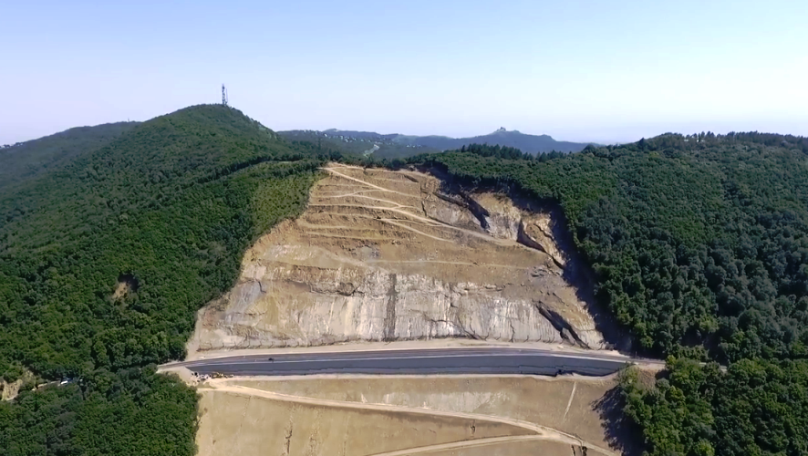
Here is the aerial view of the area showing the before/after status.

2. TECHNICAL BACKGROUND OF THE SITE
The properties of investigation area and details of the disaster based on the geological, hydrological and meteorological aspects are presented in this chapter. The main factors affecting the occurrence of the flood will be explained by referring the detailed action plan prepared just after the disaster. The action plan report includes detailed information both for area and nature of the disaster.
2.1 Geological Background
The landslide zone is located to the South-East from Tskneti village at an altitude of 1180-1300 meters above sea level. It is composed of Oligocene and lower Miocene clays, sandstones, conglomerates (Maikop series), marine molasse. The geological map is presented as follows.

2.2 Meteorological & Hydrological Background
The meteorological information about the area and hydrological conditions for landslide zone and Vere River is summarized in this section.
The meteorological data for landslide area is taken from the action plan prepared by UNDP (2015). The hydrological maps showing the flood risks and precipitation ranges are taken from DRM website.
- Due to the precipitation map, maximum 1 day precipitation for 100 years return period is estimated as 124-166 mm (Figure 7).
- Considering the flash flood assessment, the investigation area is exposed to 16-19 flash flood event for the time period for 1886-2017. This range is the highest risk class for flash flood.


3. DETAILS OF THE DISASTER
On the night of 13-14 June 2015, intense rainfall over the south-eastern part of the Vere River drainage basin area compounded the continuous and heavy rainfall of the previous ten days, resulting in a flash flood which affected the Vake and Saburtalo neighbourhoods of Tbilisi, as well other areas along the right bank of the Mtkvari (Kura) river and various places outside the city.
Additionally, a large landslide of about 1.3 million cubic metres which struck near the village of Akhaldaba (about 10 km. west of Tbilisi) poured trees, rocks, soil and other debris down a hillside into the already overflowing floodwaters of the Vere River, transforming it into a massive torrent of mud and debris.
This disaster had devastating socio-economic consequences for Tbilisi: 22 people killed, 67 families displaced, and around 700 people directly affected overall. These events severely disrupted traffic flows within the city and caused high levels of congestion (UNDP,2015).
3.1 Hydrological Facts
Based on the local database for Vere River hydrological behavior, the normal annual rate flow of river ranges between 0.26 to 1.22 cubic metres per second. The maximum rate of flow (48.3 m3/s) observed in spring or early summer. Based on the historical data of Vere River, the maximum flow rate with 100 year return period is assumed as 240 m3/s. Considering the peak flow rate records for the Vere River, the maximum rates are reported as 259 m3/s and 153 m3/s in 1960 and 1972, respectively.
The study of Gorum and Fidan (2021) claims that that most of the fatal rainfall-induced landslides occured in June and July by following the extreme peak summer rainfalls, not during the most rainy periods for Black Sea region of Turkey. The hydrological portrait of the area perfectly fits with this approach. The landslide was occured after the maximum recorded flow rate in early Summer season which is not set in the most rainy period of the year (UNDP,2015).
In 4th June 2015, the maximum flow rate is measured as 155 m3/s. In 13-14 June 2015, the maximum flow rate reaches to 468 m3/s, almost 2 times higher than the maximum design flow rate for 100 year return period. This measurement proves that, the rainfall is extraordinary and not possible to scale for any hazard assessment. Considering the precipitation measurements and maximum flow rate, the landslide may be classified in "rainfall-induced" category.
The recorded flood flow rates per peak precipitations for Vere River is given as follows

Rain gauge stations in Tbilisi recorded 60% of the city’s average annual rainfall along the 75 days period before the landslide. This situation makes the ground conditions saturated and prone to large scale displacements. As a result of this case, multiple landslides and flooding caused many causalities and considerable damage for both in the upper drainage basin and the Vere River corridor which runs through Tbilisi.
3.2 Debris Flow Mechanism
The Tskneti landslide can not be defined by increased moisture effect which brings down moving rocks to sliding consistency. In case of such a landslide, the inclination of the different layers (soil/rock) plays significant role in movement of debris flow. In this mechanism, the gravitational movement under the block-crawl regime covering at around 300 meters along with the movement significant quantity of sandstone blocks and fractured rocks remain on the slope. The flowing volume is liquid-soft state. After appearing in the riverbed with a significant inclination, it transforms into a typical debrisflow movement regime, the rocks-muddy stone material hits with great energy on the bed of the Riv.Vere Gorge and congests it with short intervals increasing the level of Riv. Vere up to 3 - 4 meters.

4. ACTION PLAN AND REMEDIATION WORKS
After the disaster, UNDP has prepared an action plan for 3 stages including short-term, medium-term and long-term actions.
As a part of the action plan, the site investigation including both drilling and geophysical surveys on the main landslide zone have been conducted. The scope may be summarized as follows:
- 9 boreholes drilling along the failure zone, 10 sets of VES measurement have been applied.
- Due to the geophysical investigation, the main observed layer properties are given as follows
The main rock layers – sandstones and conglomerates with argillite intercalations are represented by two layers based on the values of resistivity.
a) Highly weathered sandstones with argilite and conglomerate intercalations: 100-180 ohm.m resistivity,
b) Slightly weathered sandstınes with argilite and conglomerate intercalations: 175-330 ohm.m resistivity
The GE view of investigation points are presented with following figure by reflecting the area of interest both in original view and baseline map added.

4.1 Proposed Solutions for Reconstruction of Roadway
The remediation works for landslide-prone areas began by the action plan presented in 2015 by UNDP. The development of a proper repairing method of damaged roadway at the epicenter of landslide took 3 years approximately, from 2015 to the end of 2018. During this process, a multidisciplinary international technical team came together from many fields of engineering; geology, engineering geology, hydrology, geotechnical and structural. The experts from Austria, Germany, Georgia, Italy, Russia, Slovakia, Turkey and Switzerland have contributed in the decision making of proper reconstruction method.
As a first step, the sliding slope at the main landslide area is cleaned from the sediments. Total volume of displaced sediment mass is equal to 0.50 million cubic meters, approximately. (Kuparadze, 2019)

For the determination of reconstruction method, different solutions have been evaluated. The general summary of approaches to mitigate potential stability problems caused by landslides are categorized by Holtz and Schuster (1996).


The roads to be reconstructed is shown in following figure. T1, G1 and W1 sections are to support the Tskneti-Samadlo road platform while the A1 section represents the Akhaldaba road which was completely destroyed. T1 zone is the longest and the most challenging part of the rehabilitation project. T1 area is placed at the center of landslide-induced debris flow. As a joint decision of all experts and authorities, the proposed construction method is to be applied in W1 section as a trial at first. Due to the performance of the method both for technical and construction aspects, T1 section would be rehabilitated with the same method, respectively.

The remediation classification for sections referring Holtz and Schuster (1996) approach is listed in following table


4.2 Hybrid Solution for W1&T1 Sections
W1 and T1 sections are very close to the main landslide zone. Therefore, a complex retaining structure system is needed to support the new road platform. The solution may be defined as as “hybrid” retaining structure which is the combination of anchors, reinforced concrete retaining wall and Mechanically Stabilized Earth (MSE) wall.
For soil nail stabilization in active landslides, Holtz and Schuster claimed that, “There appear to be no published cases in which soil nailing has been used to stabilize active landslides or moving slopes.” However, Turner (2005) published a case study paper called “Landslide Stabilization Using Soil Nail and Mechanically Stabilized Earth Walls: Case Study” describing the “Elbow Slide” issue gives very useful recommendations for using soil nails and MSE wall in landslide stabilization. The hybrid retaining structure system which is combining the soil nailing and MSE walls were used to stabilize damaged road section. See the typical section for Elbow Slide Case as follows

The proposed section for T1 and W1 (See following sketch) is a kind of modified version of Elbow Slide section. In this system, instead of lower soil nail wall, reinforced concrete toe wall with soil nails are used to stabilize the fill slope and obtain a sufficient platform for MSE wall erection. The soil nail design considerations are valid for this application, by their mission of stabilizing the fill slope with adequate length and spacing against active landslide movement.
The key notations for composite retaining system are given as follows:
- Reinforced concrete base wall is preferred in order to stabilize the toe section. The anchors are applied along the reinforced concrete wall with an appropriate pattern. Reinforced concrete wall is also efficient by obtaining a flat platform for upper MSE wall construction.
- The another benefit for using reinforced concrete wall is the reduction of the total height of the MSE wall. This approach gives a chance to reduce the proposed strip lengths.
- Reduction in MSE wall height leads to make an optimization in excavation works which would be necessary to obtain sufficient space for strip placing. As a result, shortening the strip lengths provides a remarkable reduction in excavation volume at slope face. If the strip reduction would not be considered, additional excavations on unstable slope would possibly trigger the new landslides during construction sequence.
- MSE wall with steel strip reinforcement is used at the upper section. The MSE wall is founded on the compacted coarse-grained structural fill behind the reinforced concrete toe wall. By obtaining relatively good foundation soil conditions, the MSE wall is designed by using trapezoidal strip distribution (Shorter strips at the bottom sections of the wall). The total amount of steel strips are reduced which leads to a cost-effective solution. It is noted that the trapezoidal strip distribution is feasible only if the foundation soil conditions are sufficient (SPT-N>50) against any bearing capacity or settlement issues (FHWA).


5. MONITORING & EARLY WARNING SYSTEM (EWS) DETAILS
As a part of the action plan for landslide remediation works, the monitoring set is designed for major landslide area including inclinometers, extensometers, crack meters, piezometers are implemented to the site. All set is aiming to build up a early warning system for any potential landslide to be occurred in the same area.

In addition to monitoring plan, two additional boreholes are drilled with the depth of 42m and 50m at the top of the main scarp of the landslide. Inclinometer readings are collected from these boreholes to detect any possible active displacement.
Five piezometer installation have been completed for the purpose of observing any groundwater changes in time as a hydrological aspect of work. Meteorological station is implemented to measure precipitation magnitude and temperature with humidity.
The inclinometer readings shows that there is a slight shear movement in landslide area depth to 30 m approximately . The monitoring set gives invaluable information as an early warning system against any hazardous activity. Monitoring data is helpful for taking early actions for dissipating potential threats for the highway.
Based on the data showing that there is an active movement, simple construction precautions have been taken accordingly. After conducting the necessary procedures for stabilization, the rate of deformation detected by monitoring set have decreased dramatically (Keiling, 2021). This case shows that a proper monitoring plan for these types of landslide-prone zones are indispensable for any kind of early maintenance activities.
6. RESULTS & DISCUSSIONS
In this article, the technical aspects and background of Tskneti landslide occurred in 13-14 June 2015 is examined for related engineering aspects. The geological, hydrological, meteorological and geotechnical facts of the event are evaluated. Technical background is briefly defined.
The major Landslide caused a massive debris with 1.2 cubic millions of soil and rock fragments are dislocated from the upper edges of the Tskneti-Betania Road. This debris flow has temporarily blocked the Vere River and caused to an artificial dam on the river bed. By the effect of the enormous hydrostatic pressure caused by the accumulated water mass, the artificial dam has failed, and debris flow went through to the Tbilisi City Center. As a result of flood, 22 people dead in the disaster.
In 4th June 2015, the maximum flow rate for Vere River is measured as 155 m3/s. In 13-14 June 2015, the maximum flow rate reaches to 468 m3/s, while the maximum flow rate for River is recommended as 240 m3/s. The measured flow rate during disaster was almost 2 times higher than the maximum design flow for 100 year return period. This measurement proves that, the rainfall is extraordinary and not possible to scale for any hazard assessment. Considering the precipitation measurements and maximum flow rate, the landslide may be classified in rainfall-induced category.
The remediation methods for reconstruction of the roads are evaluated by considering various recommendations listed in literature. The decision of final methods are the result of the general agreement from the experts from disciplines including geologists, engineering geologists, geotechnical engineers and geophysical engineers. The damaged sections of the roads are classified due to the importance level and damage class. The most challenging part of the project is the construction of the road sections to be placed nearby the major landslide zone: W1 and T1 sections.
The details of the technical solution for all sections are presented in Section 4. A composite retaining system including Mechanically Stabilized Earth (MSE) wall, reinforced concrete wall and soil nailing is applied in W1 area which is relatively limited work scope. After the adequate performance of the system both for design and construction aspects, the main landslide-prone area called T1 was constructed by following the same method of design and construction. The construction works are completed by the end of 2018, approximately 3 years after the landslide occurrence.
As an important part of the action plan, the monitoring studies have been conducted on major landslide area. The monitoring plan includes the periodic measurements of displacements, precipitation range, groundwater level changes, climatic changes etc. The monitoring set works efficiently for the collection of necessary data to develop a simplified Early Warning System (EWS) at the major landslide zone: T1 area.
After the completion of the construction, the monitoring system shows the signs of ongoing movements which can be a threat to the safety of project. The early warning system is very helpful to define the possible problems at very early stages so that the additional maintenance works would be carried out.
In brief, landslide stabilization projects shall be classified as a multidisciplinary study including geology, hydrology, meteorology, geotechnical working field. A remediation project shall not be limited to construct the damaged structures in a very short time. The simple reconstruction procedure without any action plan ignoring the possible reasons of the disasters will not be the proper solution. A comprehensive study of related engineering fields is mandatory: Both for the detecting the possible reasons and proper engineering solutions. A “short term” solution without any technical background would not be able to solve the issues; the similar issues would be repeated in a very short time, probably.
Monitoring procedures are also very valuable process for landslide mitigation projects. This step is very crucial by defining the landslide mechanism and helps engineers to take necessary precautions on time. Tskneti landslide provided many engineering know-hows for future remediation works of similar problems.
7. REFERENCES
- Berg, R.R., Christopher, B.R., Samtani, N.C., (2009). "FHWA-NHI-10-024: Design of Mechanically Stabilized Earth Walls and Reinforced Soil Slopes-Volume:I" Technical Manual , Woodbury USA
- CENN & ITC (2018) – Web Atlas of Georgia
- Gaprindashvili G, Gaprindashvili M, Tsereteli E (2016) Natural disaster in Tbilisi City (Riv. Vere Basin) in the Year 2015. Int J Geosci. 7 (9):1074–1087.
- Görüm, T., Fidan, S. (2021) Spatiotemporal variations of fatal landslides in Turkey. Landslides 18, 1691–1705 https://doi.org/10.1007/s10346-020-01580-7
- Gudjabidze, G. E. (2003): Geological Map of Georgia 1 : 500.000. Georgian State Department of Geology and National Oil Company "Saqnavtobi".
- Holtz, R. D., and Schuster, R. L. (1996). “Stabilization of soil slopes.” Chap. 17 in Landslides: Investigation and mitigation, Special Report 247, A. K. Turner and R. L. Schuster, eds., Transportation Research Board, National Academy Press, Washington, D.C., 439–473.
- Keilig, Klaus & Bauer, Markus & Neumann, Peter & Thuro, Kurosch. (2021). Towards an Early Warning System for Instable Slopes in Georgia: The Large Tskneti-Akhaldaba-Landslide. 10.1007/978-3-030-60311-3_34.
- Kuparadze D., Pataridze D., (2019), “Engineering Solution of the Catastrophic Landslide Areas (By the example of Georgia)” Proceedings of the IX International Scientific and Practical Conference International Trends in Science and Technology,– Vol.1 pp:9-17, Warsaw, Poland.
- Neumann, Peter & Bauer, Markus & Haidn, Markus & Keilig, Klaus & Menabde, Zurab & Dumbadze, Dimitri. (2018). Geological and geotechnical findings of the catastrophic debris flow near Tskneti, Georgia, June 2015.
- Turner, John P., and Wayne G. Jensen. (2005) "Landslide stabilization using soil nail and mechanically stabilized earth walls: case study." Journal of Geotechnical and Geoenvironmental Engineering 131.2 pp: 141-150.
- UNDP—United Nations Development Programme (2015a) Tbilisi disaster needs assessment 2015. Part 1 (Final draft), 59 pp
- UNDP—United Nations Development Programme (2015b) Towards a multi-hazard early warning system for Georgia, 25 pp
- https://usgs.maps.arcgis.com
- http://www.gspltd.ge/index.php?a=main&pid=87&lang=eng
Thank you for sharing this published paper. I am really interested to have more details dealing with the concordance between geophysical assessment and on site geotechnical investigation. And more details concerning the on site localisation /position of the inclinometers. Thanks.
Supervision of Highway and Geotechnical Engineering / M.Sc in C.E
1yÇok tşk Tahır Bey. Bu yarslı çalışmalarınızın devamını diliyorum. Bununla birlikte söz konusu ettğim ağır önlemlerın maliyetının daha yüksek fakat buyuk çaplı bu tur kütlesel heyelanlarda daha etkıli olduğu da önemli kaynaklarda ve kongrelere sunulan vaka analizlerinde belirtiliyor (Prof.Dr. Durgunoğlu’nun TAG ve Gerede Otoyolu vaka analizi makaleleri iyararlı olur bu konuda) ayrıca uluslararası geoteknik uzman olarak çalıştığım için yakınende biliyorumki bu uzmanlar hele de çok uzman söz konusu ise her zaman en isabetli doğru çözümü çeşitli nedenlerle önerip hayata geçirme şansına sahip olamayabiliyorlar. O nedenle, bence bıraz araştırma, biraz da ekonomik sınırlamalar düşünülerek orta ölçelkte bir kayma için onerılebilecek bir çözümü özellikle de donatılı duvarın stabilite koşulları düşünülerek önermiş görünüyorlar. Zaten daha sonra da söz konusu heyelanda bazı kaymaların gözlenmesı ve ilave önlemlere başvurulması bu kanaatimi de kuvvetlendırıyor. Her neyse uzun dönemde önlemlerin etkili olup olmadığı monitoring görülür. Gercekten öğretıcı ve düşündürücü başarılı çalışmanızın devamını diliyorum.
Supervision of Highway and Geotechnical Engineering / M.Sc in C.E
1yMerhaba Tahir bey. Basarili heyelan vaka incelemeniz icin tebrikler. Belittiginiz dolgu topugunda betonarme istinat duvari. Donatili duvar ve zemin civisi ygulamasindan sonra inklinometre olcumlerinde bir miktar heyelan hareti gozlendigini ve ve bazi insaat onlemleri ile bunun sinirlandigini belirtiyorsunuz. Heyelanin şuddetli bir bir feyezan yagisi sonrasi buyuk hacimli bir yamac molozu kutlesinin akmasi ile olustugu anlasiliyor. Bu durumda uzun donemde tekrarlayabilecek yagislarin etkisiyle (Tiflis bolgesi bazi mevsimlerde tekrarlayan yogun yagis alabiliyor ) bu heyelanin yeniden hareketlenmesini önlemek icin taşima kapasitesi yuksek zemin ve kaya ankarajlari ile desteklenecek büyük çaplı derin kazikli duvarlar ve derin drenaj kuyulari ile şimdiden daha agir onlemler uygulanarak destekkenmesi ileride olasi can ve ekonomik kayiblari onlemek icin daha uygun olur muydu? Ne de olsa boyutu oldukca buyuk ve residuel kayma dayanimina ulasmis zemin ve kaya kosullarindan soz ediyoruz.
Engineering Geology | Geotechnics | Natural Hazards
1yGreat work Tahir!
Senior Consultant
1yElinize emeğinize sağlık.